BUILD CARD · EASY
LED Polarity & Current Limiting
Build a protected LED loop and learn why both polarity and a series resistor matter.
- Time
- 15 min
- Age
- 8+
- Pieces
- 7
- Board
- 10×7
- Build and check a 10×7 snap-grid circuit from a visual diagram.
- LED direction controls conduction, while a series resistor keeps current within a safer range.
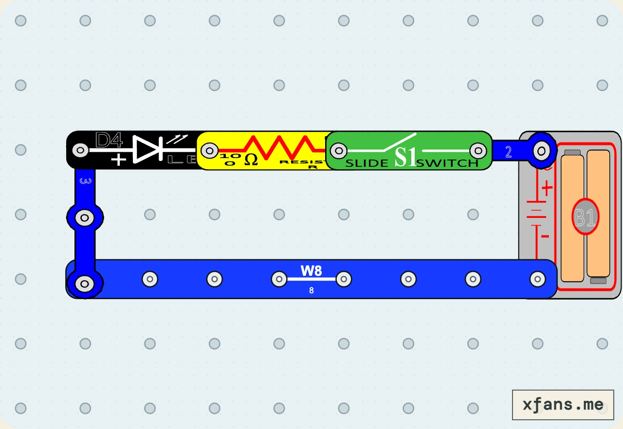
02 / PARTS CHECK
Parts list
- 1×8-snap wireconnector
- 1×3-snap wireconnector
- 1×2-snap wireconnector
- 1×White LEDsemiconductor
- 1×100 Ω resistorresistor
- 1×Slide switchswitch
- 1×3V two-cell battery holderpower
03 / ASSEMBLY
How to build the circuit
- 1
Disconnect the battery and clear the base grid before placing any part.
- 2
Match the final diagram one grid position at a time, placing connecting wires and lower layers first.
- 3
Check the direction of every LED, diode, transistor, battery, and other terminal-sensitive part.
- 4
Press every shared snap firmly, check that no wire shorts the battery, then connect power last.
04 / FIELD NOTES
How it works
An LED conducts mainly in one direction, so reversing it prevents normal light output.
The 100 Ω resistor limits current to protect the LED from excessive current.
Closing the switch completes one continuous path through the LED and resistor.
Explore more led circuit projects →
05 / TEST
Test and expected result
- What to do
- Close the switch with the LED oriented as drawn, then open it before reversing the LED.
- What to expect
- The LED lights only in the forward direction, while the 100 Ω resistor remains in series for protection.
06 / SAFETY
Build smart
- Use only the 3V battery holder.
- Never connect an LED directly across the battery.
- Open the switch before changing the LED direction.
07 / TROUBLESHOOTING
If it does not work
- Check the LED polarity marks.
- Confirm the resistor is not bypassed by a wire underneath it.
- Check every shared snap and both batteries.
08 / FREQUENTLY ASKED QUESTIONS
Questions about this circuit
What is the main idea behind this circuit?
LED direction controls conduction, while a series resistor keeps current within a safer range.
What should I check first if it does not work?
Check the LED polarity marks.
09 / RELATED BUILDS
Try a similar circuit
Continue with another build that shares the same components, ideas, or difficulty.
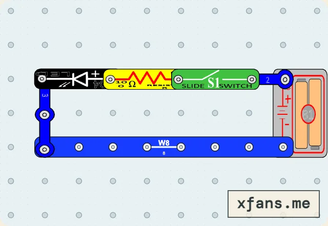
LED Reverse-Polarity Test
Reverse the protected LED and observe that polarity controls whether it can light.
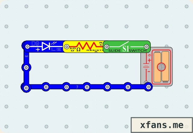
Blue LED Switch Light
Replace the color LED in manual Project 2 with a blue LED and keep the current-limiting resistor.
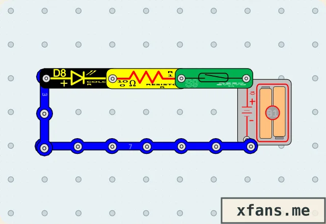
Magnetic Color Light
Bring a magnet near the reed switch to power the color LED safely.