BUILD CARD · MEDIUM
Adjustable Night-Light Threshold
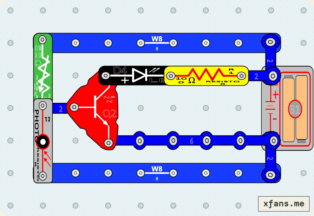
Replace the fixed bias resistor with a variable resistor to choose how dark it must be before the LED turns on.
- Time
- 35 min
- Age
- 10+
- Pieces
- 13
- Board
- 10×7
- Build and check a 10×7 snap-grid circuit from a visual diagram.
- A variable resistor changes the voltage-divider threshold that switches the transistor on.
02 / PARTS CHECK
Parts list
- 2×8-snap wireconnector
- 4×2-snap wireconnector
- 1×6-snap wireconnector
- 1×500 kΩ variable resistorsensor
- 1×Photoresistorsensor
- 1×NPN transistorsemiconductor
- 1×White LEDsemiconductor
- 1×100 Ω resistorresistor
- 1×3V two-cell battery holderpower
03 / ASSEMBLY
How to build the circuit
- 1
Disconnect the battery and clear the base grid before placing any part.
- 2
Match the final diagram one grid position at a time, placing connecting wires and lower layers first.
- 3
Check the direction of every LED, diode, transistor, battery, and other terminal-sensitive part.
- 4
Press every shared snap firmly, check that no wire shorts the battery, then connect power last.
04 / FIELD NOTES
How it works
The variable resistor changes the upper half of the light-sensing divider.
Changing its setting changes the base voltage for the same amount of light.
This moves the approximate darkness threshold at which the transistor switches the LED on.
Explore more sensor circuit projects →
05 / TEST
Test and expected result
- What to do
- Shade the photoresistor, then turn the variable resistor slowly through its range.
- What to expect
- The LED switching point moves, so you can choose how dark it must be before the LED turns on.
06 / SAFETY
Build smart
- Use only the 3V battery holder.
- Keep the 100 Ω LED resistor installed.
- Disconnect power before rearranging the sensor divider.
07 / TROUBLESHOOTING
If it does not work
- Start with the variable resistor near its middle setting.
- Move the control slowly while keeping the sensor under steady light.
- Recheck the transistor pins if the LED never changes.
08 / FREQUENTLY ASKED QUESTIONS
Questions about this circuit
What is the main idea behind this circuit?
A variable resistor changes the voltage-divider threshold that switches the transistor on.
What should I check first if it does not work?
Start with the variable resistor near its middle setting.
09 / RELATED BUILDS
Try a similar circuit
Continue with another build that shares the same components, ideas, or difficulty.
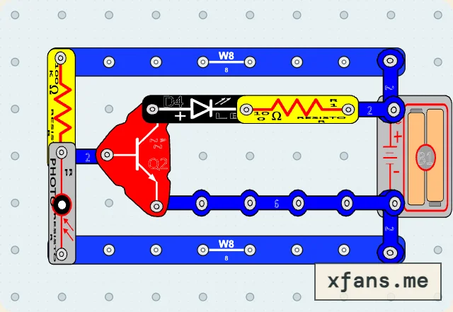
Photoresistor Night Light
Use a light-dependent voltage divider and an NPN transistor to turn an LED on in darkness.
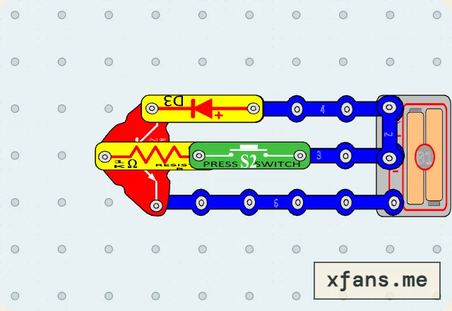
Protected Transistor Motor Driver
Add a reverse-biased diode across the motor to give inductive turn-off current a safer path.
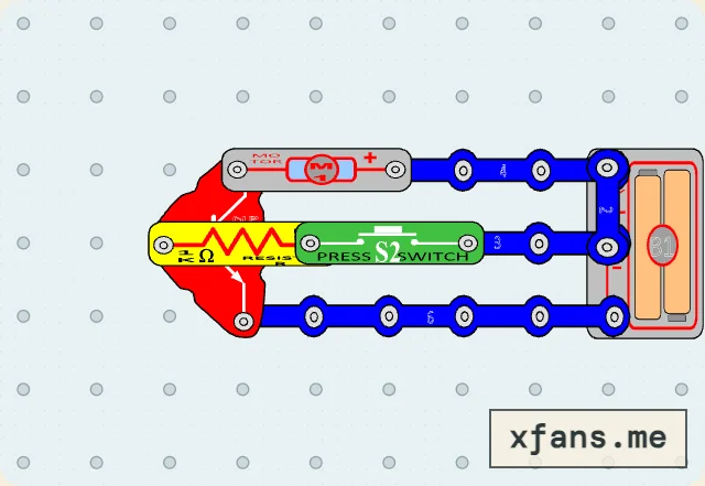
Transistor Motor Driver
Use a press switch and small base current to let an NPN transistor control a motor load.