BUILD CARD · MEDIUM
Protected Transistor Motor Driver
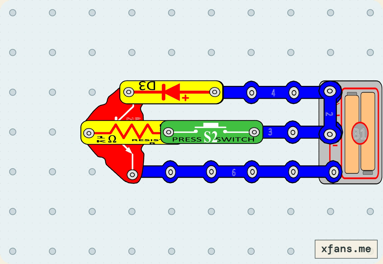
Add a reverse-biased diode across the motor to give inductive turn-off current a safer path.
- Time
- 30 min
- Age
- 10+
- Pieces
- 10
- Board
- 10×7
- Build and check a 10×7 snap-grid circuit from a visual diagram.
- A flyback diode safely recirculates inductive current when the transistor switches off.
02 / PARTS CHECK
Parts list
- 1×4-snap wireconnector
- 1×6-snap wireconnector
- 1×3-snap wireconnector
- 1×2-snap wireconnector
- 1×NPN transistorsemiconductor
- 1×Motoroutput
- 1×Diodesemiconductor
- 1×1 kΩ resistorresistor
- 1×Press switchswitch
- 1×3V two-cell battery holderpower
03 / ASSEMBLY
How to build the circuit
- 1
Disconnect the battery and clear the base grid before placing any part.
- 2
Match the final diagram one grid position at a time, placing connecting wires and lower layers first.
- 3
Check the direction of every LED, diode, transistor, battery, and other terminal-sensitive part.
- 4
Press every shared snap firmly, check that no wire shorts the battery, then connect power last.
04 / FIELD NOTES
How it works
A spinning motor is inductive and can produce a voltage spike when transistor current stops.
The normally reverse-biased diode provides a path for that brief turn-off current.
The base resistor still limits control current while the transistor switches the motor load.
Explore more motor circuit projects →
05 / TEST
Test and expected result
- What to do
- Press the control switch for a short run, then release it while observing the motor.
- What to expect
- The transistor drives the motor; the reverse-biased diode provides a safer path when current switches off.
06 / SAFETY
Build smart
- Use only the 3V battery holder.
- Disconnect power before reversing the diode.
- Keep fingers and loose material away from the motor shaft.
07 / TROUBLESHOOTING
If it does not work
- The diode must be reverse-biased during normal motor operation.
- If the motor never starts, disconnect power and recheck the diode direction.
- Check all three transistor terminals and the press-switch path.
08 / FREQUENTLY ASKED QUESTIONS
Questions about this circuit
What is the main idea behind this circuit?
A flyback diode safely recirculates inductive current when the transistor switches off.
What should I check first if it does not work?
The diode must be reverse-biased during normal motor operation.
09 / RELATED BUILDS
Try a similar circuit
Continue with another build that shares the same components, ideas, or difficulty.
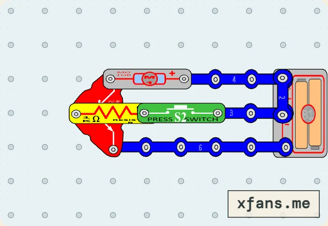
Transistor Motor Driver
Use a press switch and small base current to let an NPN transistor control a motor load.
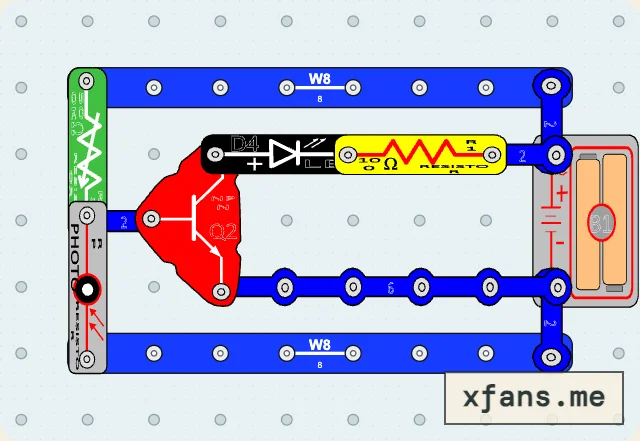
Adjustable Night-Light Threshold
Replace the fixed bias resistor with a variable resistor to choose how dark it must be before the LED turns on.
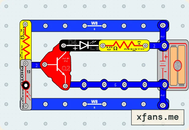
Photoresistor Night Light
Use a light-dependent voltage divider and an NPN transistor to turn an LED on in darkness.